WIFI FOXHUNT ESP8266
Yes! You are reading it correctly! With JOTI.tv we are going to let you see how to create you own WiFi Foxhunt kit. The “fox” will be made with a ESP8266-ES01 controller and some supporting components. During JOTA-JOTI we will show you how to solder all these parts together and how to create the firmware for the ESP8266. Order the components you need and follow the steps below to create you “fox’s”.
Don’t miss this and subscribe to our YouTube channel!
The components you need
Per “fox” you need the following components. During JOTA-JOTI we will create 10 foxes, make sure you order enhough compontents.
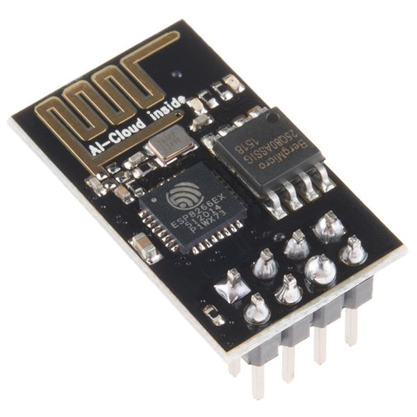
- 1x ESP8266 ESP-01 buy on eBay
- 1x LD111733 (3.3v regulator) buy on eBay
- 1x 100nf capacitor buy on eBay
- 1x 10uf capacitor buy on eBay
- 1x ESP8266 programmer buy on eBay
- 1x 18650 cell (or standard 9v battery including battery clip)
- 1x TP4065 Micro USB 18650 charging board (not needed when using a 9v battery) buy on eBay
- 1x 2x8cm prototype PCB (optional) buy on eBay
- 1x 2x4 pin double row header (optional with PCB) buy on eBay
- 1x small case
Materials you need
- Soldering iron
- Solder (tin)
- Snips (cutter)
- Tape
- Hotglue gun
- Shrink tube
- Solid core wires
- Computer with Arduino software
The Code you need
You can find the Foxhunt code on GitHub: https://github.com/JOTItv/WiFiFoxhunt
How-to manual to build the WiFi Foxhunt modules
Follow the steps below to build you own WiFi Foxhunt transmitters
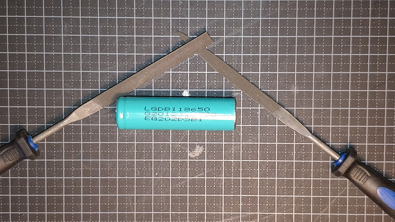
Step 1 - prepare 18650 for soldering
Recycled 18650 cells are ideal for this project. Most of the recycled cells had strips of metal spotwelded to them. Use a file to clean the ends of the cell, this also helps with soldering of the leads to the cell.
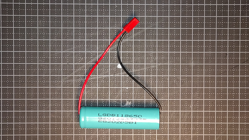
Step 2 - solder the JST leads to the 18650 cell
Use solder with a wax core. Make sure your soldering iron is above 350 degrees celcius. Make sure you work quick and not heat up the cell too much.
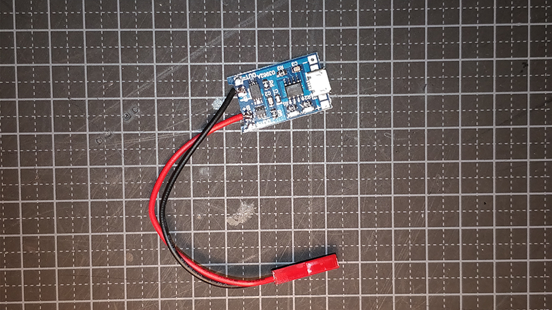
Step 3 - solder the JST leads to the TP4065 charger board
Solder the leads to the inner pads od the TP4065 board. The pads are marked with B+ and B- (B for battery).
Now you can connect the cell to charger board. Disconnect the cell before you go to the next step.
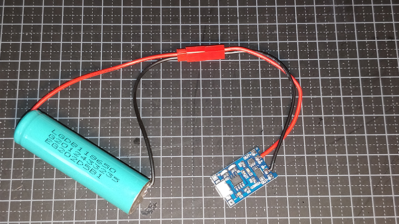
Tip: always store the cells fully charged to extend the life-time.
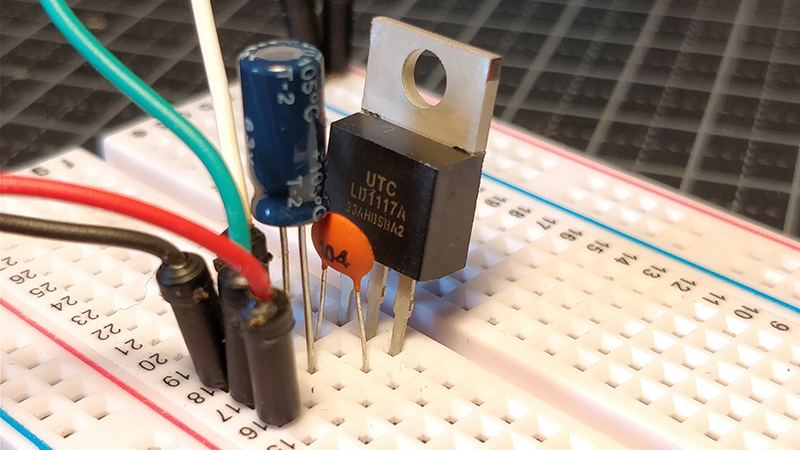
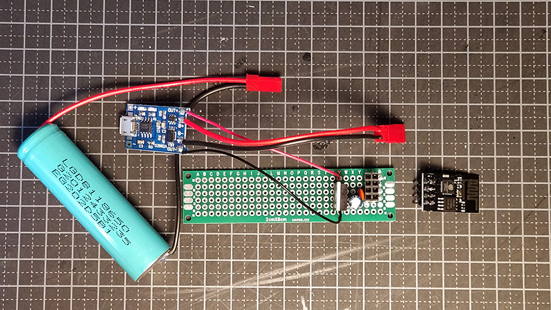
Step 4 - Test the power circuit on the breadboard
Use a breadboard to line-up all the components and to test if they work correctly before soldering them to the perf board. The output of the LD111733 must be between 3.1 and 3.4 volts.
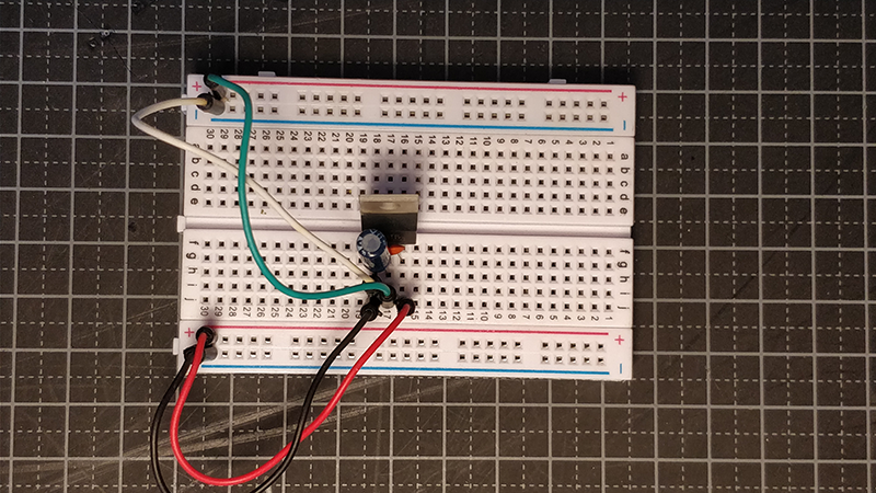
Close-up of the components on the breadboard
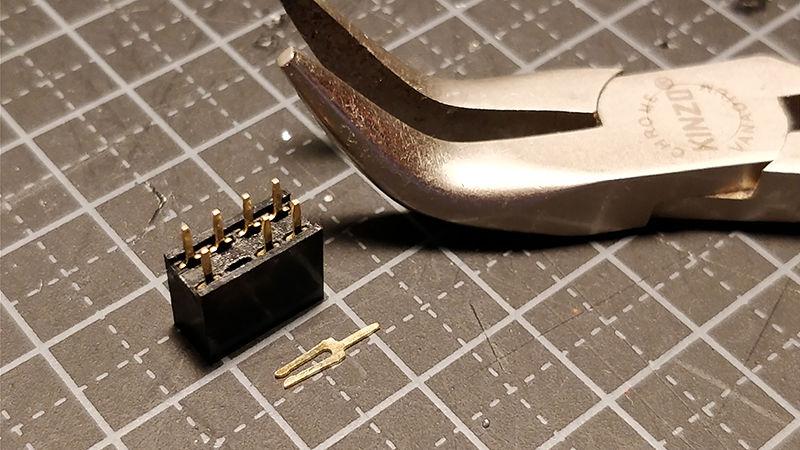
Step 5 - Prepare pin header before soldering
The ESP8266 needs two VCC connections, the standard VCC and the CH_PD pin must receive 3.3 volts. To avoid making dificult jumpers while soldering it is easier to remove one of the header pins.
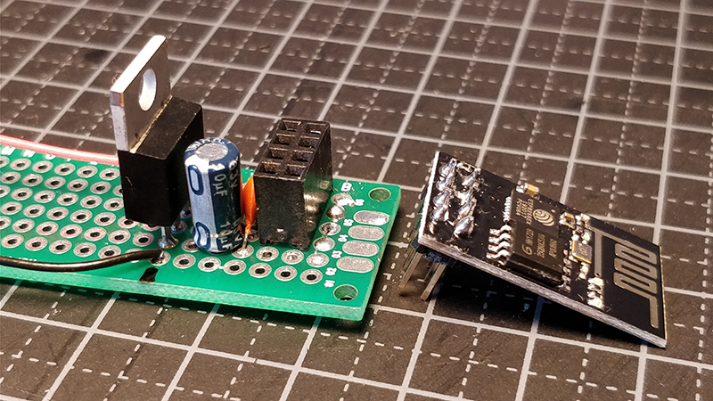
Step 6 - Solder all components to the pref board
Now all parts are ready to bring together.
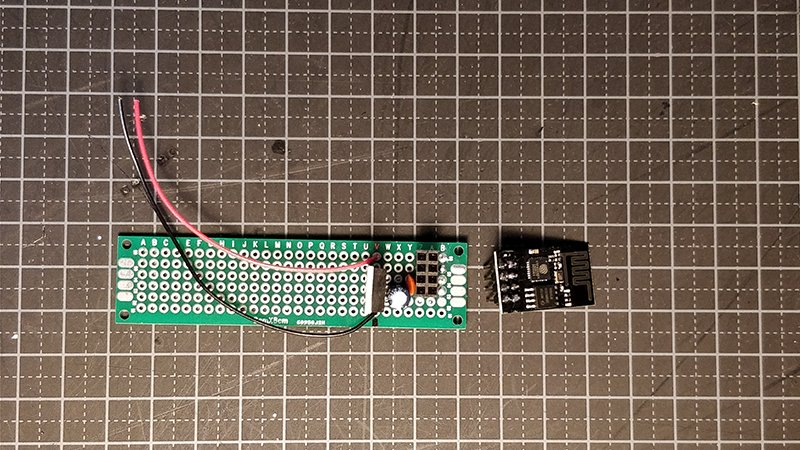
Place all the components on the board
Place all components on the perf board. Tag the leads of the components with a little bit of solder before going further. First check and align all components, all OK, now solder everything to the board.
Use the leads from the components
Bend the component leads to create a path over the holes of the perf board. This makes it easy to create the tracks.
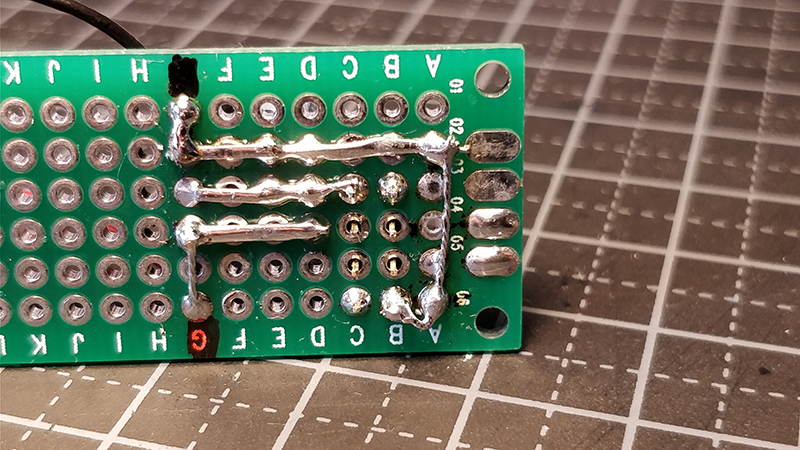
All components and wires are now soldered to the board
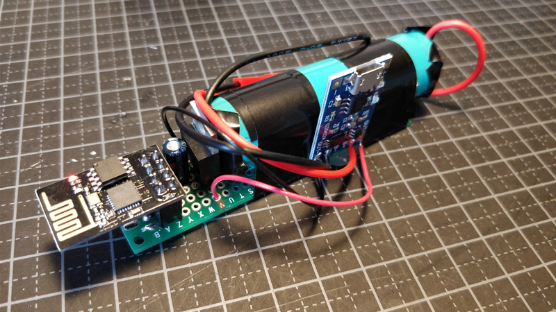
Step 7 - Bring it all together
Now you have everything ready to make the complete package.
Use hotglue to attach the charger board to the cell and perf board. This makes a strong connection.
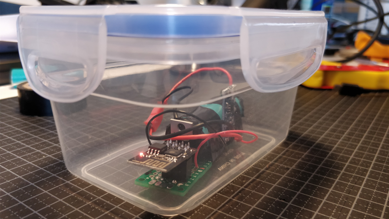
TIP: use a waterproof box to store the fox module when you use it outside
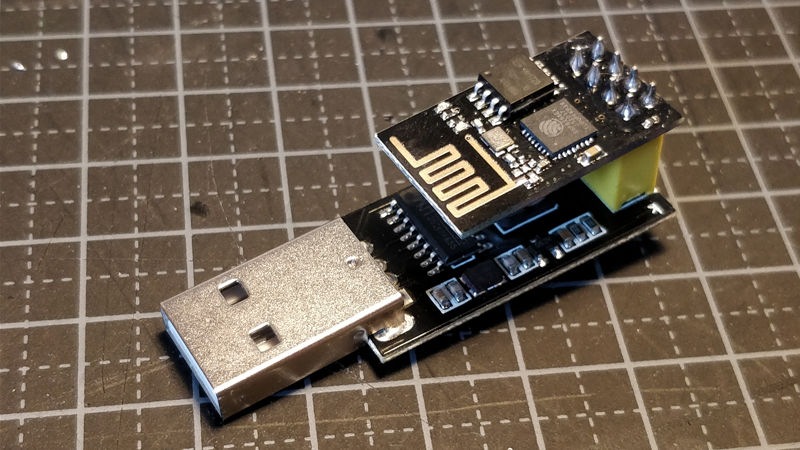
Modify the ESP8266 programmer
The standard programmer must be altered to be able to flash the ESP8266 module. A easy trick is to attach a male header punt to the back of the programmer. A jumper connection can be used to switch between normal mode and flash mode. The jumper connects the GPIO0 to GND to put the ESP8266 in flash mode.
In the image below the short part of the middle header pin is bend to short part the bottom header pin. The jumper in the picture connects the bottom pin with the middle pin, this is the normal mode. When the jumper is connected to the middle and top pin the ESP8266 is put in flash mode.
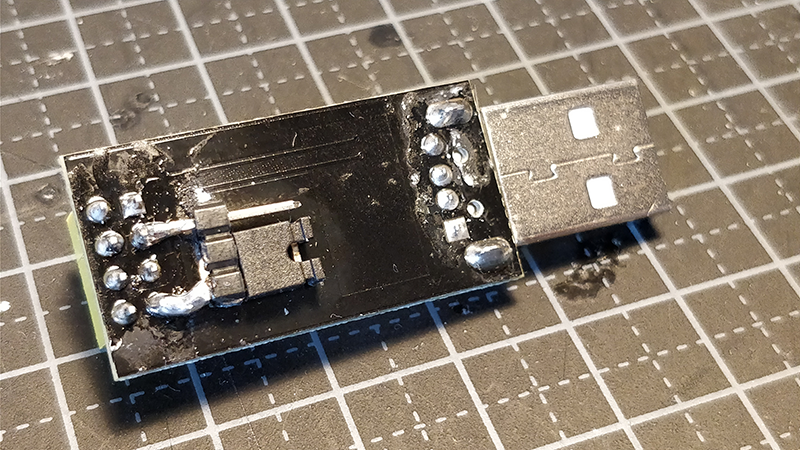
The programmer from the top
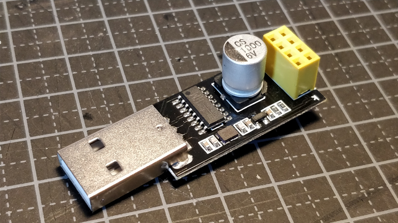
The programmer with the ESP8266 attached